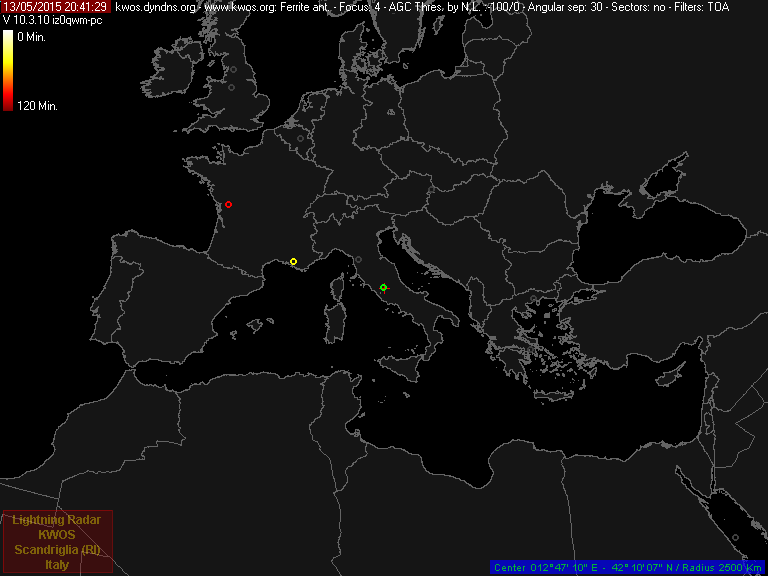
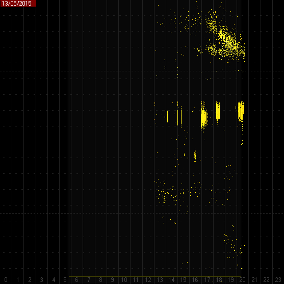
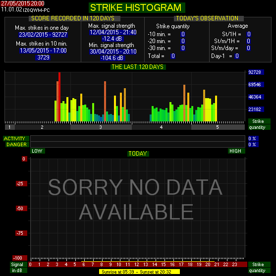
After about one year of maintenance (I have rebuilt all the circuit) the lightning radar, an invention of Frank Kooiman, is back on-line.
Now will follow a period of verification of the generated output, after which will be it put on the pages of KWOS.
At the moment you can display the screens of the software on this blog, or on the site Lightningradar.net
This system was developed as a hobby alternative to the existing
commercial Boltek lightning detector. The advantages of the
lightning radar are the low cost (€40 and up) compared to the
Boltek (€350 to €600 depending on theversion),
the extreme sensitivity of the system, and the possibility of
joining the group system via the internet. Where Boltek
detectors can detect lightning up to a range of 500km, the LR
(lightning radar) has a range of 2000 to 3000km over land and
several thousand km over water (e.g. lightning in Florida, south
America).
One disadvantage of the LR is that it is not a plug-and-play
system and therefore requires some knowledge
of electronics and
familiarity with a soldering iron. In practice, this is not
really a disadvantage since it means that
you learn a lot more about the science of detecting lightning.
The software functions as a single station showing the direction
and estimated distance, or connects with other LR stations via
the internet to perform a localisation function, displaying the
result (specific direction and distance) on a map. In addition
these maps can be uploaded to your website.
The electronics consists of
an amplifier which boosts and filters the signal from an antenna
and passes it to the soundcard of a computer (Line-in).
The lightning strikes are received using a frame antenna set at
10 kHz. At this frequency range the lightning sends impulses
over a range of several thousand kilometres. The antenna
consists of a frame, around which wire is wound in multiple
windings. The antenna measures the magnetic part of a wave and
has the advantage that it is less sensitive to interfering
electrical fields. With a single antenna, the lightning strike
can be detected but the direction cannot be measured. For this
reason a second identical antenna is mounted at 90 degrees to
the first antenna.
The direction can be calculated from the two
signals measured. It is still not possible to say for certain
that
the lightning strike occurred at one direction, exactly
opposite direction could also have been possible (+180 degrees).
This is also due to the fact that we do not know if the
lightning strike had a positive or negative charge. If you are
working with a single station, a third antenna is therefore
necessary to detect the charge and therefore the correct
direction of the strike. A single station cannot be used to
determine the exact position / distance of the strike. This can
only be estimated from the strength of the signal, since not all
lightning strikes have the same energy. Lightning Radar works in
a group of a number of stations and can therefore calculate the
correct direction and the position / distance using only 2
antennas.
Now
I have in test two ferrite antennas just like the ones used for
the TOA system. It's not simple to adapt them to the RDF hardware
but some good result is coming :-)
You can find information about
Lightning Radar on:
http://www.lightningradar.net
Use the following image to check the result from the first image.
Thoughts and ideas .. day by day as they come out of my mind ;) What I read, what I find around or what I'd like to do. If you're looking for my website, that's it: http://www.kwos.org
Saturday 29 June 2013
ADS-B Java Software
 The development of ADS-B software in Java continues. Another programmer has joined our group: i0kte, Stefano Ricciardetto. He is an expert on radar console, has worked for many years as a software programmer for the ATC.
Now the software in addition to the display of the aircraft on the maps of Nasa World Winds, allows to upload outlines which are usually employed with Basestation or Planeplotter.
The planes seen at close range, are represented in 3D.
At the moment you can add various sources ADS-B but only in SBS format (port 30003).
The icon that identifies the aircraft, the track and the direction it will be soon changed according to the ATC standards.
Currently we are investigating to solve a java heap space error that occurs about 2 days after the software is started.
The moon at perigee on June 22-23
Set to peak on Sunday, June 23, the 2013 supermoon is noteworthy not only for the remarkable  sight it will present to skywatchers but also because it will be the largest supermoon this year.
Also known as a perigee moon, the event occurs when a full moon lines up with the Earth and the sun at a specific point in its orbit, called the lunar perigee. That's the point at which the moon is nearest to Earth as it traces its elliptical path around our planet.
Since it's closer to us, the moon appears up to 14 percent bigger and 30 percent brighter than usual. Coined by astrologer Richard Nolle, the term "supermoon"essentially means a bigger and brighter full moon.
But what makes Sunday's supermoon so special?
While skywatchers will be able to spot another supermoon in July, the moon will not be this close again until August 2014.
 sight it will present to skywatchers but also because it will be the largest supermoon this year.
Also known as a perigee moon, the event occurs when a full moon lines up with the Earth and the sun at a specific point in its orbit, called the lunar perigee. That's the point at which the moon is nearest to Earth as it traces its elliptical path around our planet.
Since it's closer to us, the moon appears up to 14 percent bigger and 30 percent brighter than usual. Coined by astrologer Richard Nolle, the term "supermoon"essentially means a bigger and brighter full moon.
But what makes Sunday's supermoon so special?
While skywatchers will be able to spot another supermoon in July, the moon will not be this close again until August 2014.
Sunday 16 June 2013
Meteors, meteors...June Lyrids
The June Lyrid meteor shower is coming.
This shower is active during June 10 to 21, producing predominantly blue and white meteors at a maximum hourly rate of 8 per hour on June 15 (λ=84.5°). At maximum the radiant is located at α=278°, δ=+35°. The average observed magnitude of this shower is near 3, while about 32% of the meteors leave trains.
Observations from 46 observers, totalling 172 man-hours, were gathered and analyzed by Keith B. Hindley of the British Astronomical Association. The observations covered the period of June 11.5 to 21.0 (Solar Longitude=80.2 deg to 89.2 deg) and the total number of June Lyrids observed was 363. Against a fairly constant sporadic meteor rate of 8.7 per hour, the June Lyrids displayed a broad maximum of about 6 per hour during June 13 to 17, with a sharp peak of 9 per hour on June 16.0 (Solar Longitude=84.5 deg). The average magnitude was found to be 2.0 and 32% of the shower's meteors showed persistent trains. Colors displayed a prominence of white, as did sporadic meteors, however, there was also a large number of blue meteors. The exact percentages of colors seen among the June Lyrids were as follows: 33%, blue, 52%, white, 9%, yellow, and 6%, orange-red.
 Although observations continued after 1969, there seemed an indication that the meteor rates of 8 or 9 per hour had vanished. In 1971, about 215 hours of observations were acquired by 26 observers from Canada and the United States. The shower's ZHR irregularly varied during the period of June 10 to 24, with
maximum peaks of 1.3 to 3.5. The radiant of the stream was determined from 37 meteors plotted by an Ottawa observing group from observations made during June 14 to 17, with the result being RA=278.3 deg, DECL=+41 deg.
 Observations in 1974 indicated a resurgence of activity. The shower's discoverer, Dvorak, observed on four nights during mid-June, with the following average hourly rates (not ZHRs) being noted: June 14/15, 2.9, June 15/16, 6.5, June 16/17, 6.2, June 17/18, 2.3. Dvorak added that the meteors moved swiftly, with the majority being bluish-green. Also, in 1974, Nolthenius, Alan Devault and Bob Fischer (all of California) observed during 7 nights between June 9 and 22. Overall, they observed 32 June Lyrids, with the average magnitude being determined as 3.09. Slightly less than half of their total number of June Lyrids were seen on the shower's night of maximum (June 15/16). The average number of meteors seen from this radiant was 4 per hour.
During 1975, observations were quite scarce. Between June 6 and 15, Norman W. McLeod III (Florida) saw only 2 June Lyrids, while, during the period June 9 to 14, Mark Adams (Pennsylvania) noted 5 members, with 4 coming in less than 3.5 hours on the final date of observation. Finally, Paul Jones (St. Augustine, Florida) observed for 3 hours on the night of maximum and detected 20 June Lyrids.
This shower is active during June 10 to 21, producing predominantly blue and white meteors at a maximum hourly rate of 8 per hour on June 15 (λ=84.5°). At maximum the radiant is located at α=278°, δ=+35°. The average observed magnitude of this shower is near 3, while about 32% of the meteors leave trains.
This meteor shower was discovered on the evening of June 15, 1966, by S. Dvorak (California, USA) while camping out in the San Bernardino mountains. His attention had been drawn to the region of Lyra by a very bright meteor that moved swiftly to the northeast through that constellation. Another meteor was noted a short time later and Dvorak began plotting additional meteors. After 1 1/2 hours he had managed to plot 16 meteors, of which 13 appeared to originate from a hitherto unknown radiant located at RA=278°, DECL=+30°. Just a few hours later, F. W. Talbot (Cheshire, England) independently discovered the radiant at RA=275.5°, DECL=+30°, and noted an hourly rate near 9.
Moonlight from a waning moon interfered with observations in 1967, but, in June 1968, confirmation of this shower's existence came from Richard Nolthenius (Hacienda Heights, California). During one hour on the 15th, he detected 8 June Lyrids, while a similar hour on the 17th revealed 7. Observations of this shower have continued annually ever since, however, to date, the most elaborate study of this shower was made from observations obtained during 1969.
The average radiant, as determined by Hindley, was found to be RA=278 deg+/-2 deg, DECL=+35 deg+/-3 deg. From this position, a parabolic orbit was calculated, which revealed a close, but "not convincing" similarity to comet Mellish (1915 II). This comet possesses a slightly hyperbolic orbit with an eccentricity of 1.0002. A radar orbit obtained by Zdenek Sekanina from observations made at Havana, Illinois, in 1969, actually seemed to strengthen the similarity between the June Lyrids and 1915 II, except for the fact that the radar orbit revealed a period of 2.94 years. These orbits are compared later.
 Although observations continued after 1969, there seemed an indication that the meteor rates of 8 or 9 per hour had vanished. In 1971, about 215 hours of observations were acquired by 26 observers from Canada and the United States. The shower's ZHR irregularly varied during the period of June 10 to 24, with
 maximum peaks of 1.3 to 3.5. The radiant of the stream was determined from 37 meteors plotted by an Ottawa observing group from observations made during June 14 to 17, with the result being RA=278.3 deg, DECL=+41 deg.
In 1972, the shower again showed a poor return. Meteor News combined the observations of 20 observers, made during June 9 to 22, and found the maximum ZHR to be only 2.3---a value that came on June 15/16. What the observations also revealed were activity levels between 1.2 and 1.3 during June 12 to 15, which suddenly jumped to 2.3, then rapidly fell to only 0.3 by the night of June 18/19. Thus, the shower's date of maximum and variation of activity levels closely reflected those noted in 1969, but the ZHRs were typically down by about 6 or 7 meteors per hour!
 Observations in 1974 indicated a resurgence of activity. The shower's discoverer, Dvorak, observed on four nights during mid-June, with the following average hourly rates (not ZHRs) being noted: June 14/15, 2.9, June 15/16, 6.5, June 16/17, 6.2, June 17/18, 2.3. Dvorak added that the meteors moved swiftly, with the majority being bluish-green. Also, in 1974, Nolthenius, Alan Devault and Bob Fischer (all of California) observed during 7 nights between June 9 and 22. Overall, they observed 32 June Lyrids, with the average magnitude being determined as 3.09. Slightly less than half of their total number of June Lyrids were seen on the shower's night of maximum (June 15/16). The average number of meteors seen from this radiant was 4 per hour.
Interest in the June Lyrids seems to have waned in the latter half of the 1970s and into the 1980s, with only a few individuals continuing to monitor the shower annually---many of them rarely observing around the time of the shower's established date of maximum. As is evident from the previously listed observations, activity from this radiant can be virtually nonexistent on dates other than June 15 and 16, due to the June Lyrids' very pronounced peak of activity.
In 1979, observers in Texas observed on June 15/16 and 17/18, with meteors being seen to reach nearly 2 per hour on the latter date. In Quebec, F. Roy observed during June 16/17, 18/19 and 20/21 and noted 12 meteors in about 3.5 hours---certainly marking the most activity seen from this radiant since 1974. During 1980, the enhanced rates still seemed present, with John West (Texas) noting 18 meteors in only 5 hours on June 13/14 and 14/15. Since 1980, the shower's activity has again dropped to maximum rates of about 1
per hour.
per hour.
A search for pre-1966 observations of this shower has not revealed many clues to the shower's history. From observations by G. Zeziolli, G. V. Schiaparelli isolated 11 meteors observed on June 14, 1869, from a radiant of RA=280 deg, DECL=+35 deg. No convincing June Lyrid radiants were observed by members of the American Meteor Society prior to 1966, nor were any observations present among the extensive visual radiants obtained by A. S. Herschel, A. King, C. Hoffmeister or E. Opik.
Aside from the 1969 study by Hindley, studies of the June Lyrids have been rare, with the only other information gathered on the individual meteors involving the average magnitude. John West observed 59 June Lyrids during 1967 to 1982, and found the average magnitude to be 3.02. During 1967 to 1981, R. Hill (North Carolina, USA) observed 65 June Lyrids and found the average magnitude to be 2.71.
HFDL Monitoring (ARINC spec. 635-3)
While I'm continuing my studies on navigational aids, I've just bought two new books (Navigazione Aerea e Electronic Installation Instructions for ILS facilities), I begun the reception of another Aeronautical communication system: HFDL.
Aircraft utilize HF communications when VHF (Line of Sight) communications is not sufficient. The primary usage of HF is for Trans-oceanic flights. Trans-oceanic flights communicate with ground stations via HF for position reports and other purposes. Another utilization of HF communications is for HFDL or High Frequency DataLink. Finally Military Aircraft (MILCRAFT) utilize HF for operational and training.
HFDL is a HF data link protocol, defined in ARINC spec 635-3.
It may be described as some sort of HF ACARS.
Transmissions on HF are in USB on a sub carrier of 1440 Hz with a symbol speed of 1800 baud.
Modulation is 2-PSK, 4-PSK or 8-PSK with effective bit rates of 300, 600, 1200 or 1800 bits/sec.
The HFDL service is operated by ARINC as GLOBALink service through a worldwide network of HF stations.
On board the aircraft, a pilot simply sets one of the HF radios to "DATA" after takeoff, and the HFDL seamlessly integrated into the flight management system.
The ACARS will use HF or VHF depending on what is available. The HF part of the system is usually taken out of "DATA" mode before landing to prevent inadvertent RF exposure to ground personnel, since the system will start to tune around and seek a connection to the network as HF conditions change.
HFDL signals are present whenever the HF bands are open, and are actually more robust than voice transmissions. The author has often gotten solid copy of HFDL transmissions while finding voice from the same geographic area to be a struggle. Even when conditions are marginal, a scan of the current HFDL frequencies will often yield readable data. With a suitable computer controlled radio, the HFDL nets can be followed up and down the spectrum with the diurnal cycle of the ionosphere.
More information could be found on:
Tuesday 11 June 2013
VOR - Ground installation - 1/2
The VOR system operates on frequencies between 108 MHz and 117.95 MHz. Channel separation is 50 kHz and the signals have a horizontal polarisation.
Frequencies between 108 MHz and 111.95 MHz are primarily used for the localiser part of the ILS but can be shared with short range VORs, or so-called terminal VORs. The VOR uses frequencies having an even decimal as the first digit after the last MHz digit, while localizers use odd decimals. When assigning a VOR to this part of the frequency band, it is an essential requirement that it does not interfere with an adjacent ILS channel.
The frequencies from 112.00 to 117.95 MHz are solely used by VOR, both on odd and even frequencies
108.35 Localizer
 The rotation of the limacon creates an effective amplitude modulation of 30 Hz. The VOR receiver splits these two signals into the two original components. The two signals are processed through different channels and the phase of the 30 Hz modulations of the fixed REF signal and the VAR signal are compared in a phase comparator. The phase difference between these two signals is directly proportional to angular position with reference to the VOR station.
Frequencies between 108 MHz and 111.95 MHz are primarily used for the localiser part of the ILS but can be shared with short range VORs, or so-called terminal VORs. The VOR uses frequencies having an even decimal as the first digit after the last MHz digit, while localizers use odd decimals. When assigning a VOR to this part of the frequency band, it is an essential requirement that it does not interfere with an adjacent ILS channel.
The frequencies from 112.00 to 117.95 MHz are solely used by VOR, both on odd and even frequencies
108.10 Localizer 112.00 VOR
108.15 Localizer 112.15 VOR
108.20 T-VOR 112.10 VOR
108.25 T-VOR
108.30 Localizer 117.95 VOR 108.15 Localizer 112.15 VOR
108.20 T-VOR 112.10 VOR
108.25 T-VOR
108.35 Localizer
The VOR radiates an RF carrier with which are associated two separate 30 Hz modulations. The phase of one of these modulations is independent of the point of observation (i.e., reference phase). The phase of the other modulation (variable phase) is such that, at a point of observation, it differs from the reference phase by an angle equal to the bearing of the point of observation with respect to the VOR. The two separate modulations consist of the following:
A sub-carrier of 9960 Hz, frequency modulated at 30 Hz, modulating the carrier to a nominal depth of 30%. This 30 Hz component is fixed independent of the azimuth and is termed the reference phase.
A 30 Hz component, modulating the carrier to a nominal depth of 30%. This 30 Hz component is caused by a rotating antenna producing a change in phase with azimuth and is termed the variable phase.
When the two signals (VAR & REF) are mixed together, the resulting polar diagram will be a cardioid, but unlike the cardioid of the ADF, this does not have a «null» position. We call it a «limacon». It rotates at 30 revolutions per second.
 The rotation of the limacon creates an effective amplitude modulation of 30 Hz. The VOR receiver splits these two signals into the two original components. The two signals are processed through different channels and the phase of the 30 Hz modulations of the fixed REF signal and the VAR signal are compared in a phase comparator. The phase difference between these two signals is directly proportional to angular position with reference to the VOR station.
As explained, magnetic North is the normal reference for the radials, so when 0° phase difference is detected, the receiver is on the 360° radial from the station. The figure on the left shows the phase difference and variable signal at the cardinal points.
Sunday 9 June 2013
VOR - What is it ?
The television emitters on the band 50-70MHz are being switched off so we need other emitters always on, with known positions suitable for meteor scattering.
The 88-108band is too crowded, so, on the adiacent band we can find the navaids for the aeronautical world: VOR, DVOR and ILS.Before thinking about using the navaids for meteor scattering, let's see how they work.
VOR is an abbreviation for “VHF Omnidirectional Radio Range”, which implies that it operates in the VHF band. Short range infers that ranges up to 200 NM can be expected.
It is still the most commonly used short-range aid. As opposed to the NDB, which transmits a non-directional signal, the signal transmitted by the VOR contains directional information.
The principle of operation is bearing measurement by phase comparison. This means that the transmitter on the ground produces and transmits a signal, or actually two separate signals, which make it possible for the receiver to determine its position in relation to the ground station by comparing the phases of these two
signals. In theory, the VOR produces a number of tracks all originating at the transmitter. These tracks are called «radials» and are numbered from 1 to 360, expressed in degrees, or°. The 360° radial is the track leaving the VOR station towards the Magnetic North, and if you continue with the cardinal points, radial 090° points to the East, the 180° radial to the South and the 270° radial to the West, all in relation to the magnetic North.
Before we look in detail at how the system works, I can make it easier to understand with an example.
Think of a lighthouse at sea and imagine the white light rotating at a speed of one revolution per minute (60 seconds). Every time this white narrow beam passes through Magnetic North, a green omnidirectional light flashes. Omnidirectional means that it can be seen from any position around the lighthouse. If we are situated somewhere in the vicinity of the light sources and are able to see them, we can measure the time interval from the green light flash until we see the white light. The elapsed time is directly proportional to our position line
in relation to the lighthouse.
Here’s how brits Bramson and Birch describe it in their 1984 book, Radio Navigation for Pilots:
PURPOSE OF THE EQUIPMENTTo facilitate en-route navigation along selected radials and to provide references for holding and let-down procedures.PRINCIPLE OF THE AIDVOR is a relatively short range radio navigational aid operating between 108 and 118MHz in the VHF band. It is a pilot interpreted aid comprising an airborne Navigation Receiver capable of being tuned to 100 or more frequencies and aConverter/Indicator which accepts signals from the navigation receiver translating them into simple indications on an instrument face. The airborne equipment is used in conjunction with a system of VOR beacons, most of them situated within the airways network.To understand the principles of VOR it is necessary to have a superficial knowledge of the radio wave itself.In the section on electro-magnetic energy the basic wave cycle was described (page 50). In essence the state of the electric current within a cycle (i.e. positive or negative strength) is constantly varying with time. Indeed at any particular time the development of the wave may be identified e.g. half maximum positive rising: maximum negative: zero raising to positive etc. As already explained such a state of development is known as a Phase.Imagine a radio beacon designed to radiate two beams, one running north and the other running south. And suppose each beam consists of two waves, the north beam emitting its phases in unison and the south beam with its waves at opposite phases (Fig. 41). An electronic device capable of measuring the difference in phase between two radio waves would, in this case be able to tell the operator when he was within the north beam or south beam. In other words the equipment is able to compare the differences between the phases of two simultaneously transmitted waves and since it uses this principle VOR is known as a Phase Comparison aid.
Fig. 41.THE VOR TRANSMITTERUsing the principle of phase comparison the VOR radiates a Reference Signal (REF) in all directions, its phase remaining constant throughout the reception area. A second signal, transmitted as a narrow beam, is arranged to sweep like a lighthouse through 360° (VAR Variable Signal). As it sweeps, the phase of the beacon is constantly altering so that its phase comparison with the fixed reference signal will change according to its position relative to the beacon (Fig. 42). In effect a VOR beacon emits an infinite number of beams or Radials through 360°, each possessed of unique differences in phase between the two signals. It therefore follows that with the air of equipment designed to measure or compare the two phases and translate these into headings from the beacons (radials), a pilot would be able to locate his aircraft in relation to the known position of that beacon. The VOR Beacon is adjusted to transmit radials related to Magnetic North.
Fig. 42.In a next post I'll explain the ground installation and the frequency used.
Wednesday 5 June 2013
Radio meteor scatter
Radio meteor scatter is an ideal technique for observing meteors continuously. Meteor trails can reflect radio waves from distant transmitters back to Earth, so when a meteor appears one can sometimes receive small portions of broadcasts from radio stations up to 2000 km away from the observing site.
The general principle of meteor observation by forward scattering of radio waves off their trails is easy to understand.
The general principle of meteor observation by forward scattering of radio waves off their trails is easy to understand.
A lower VHF radio receiver (30-100 MHz) is located at a large distance (about 500-2000 km) from a transmitter at the same frequency. Direct radio contact is impossible due to the curvature of the Earth. When a meteor enters the atmosphere, its trail may reflect the radio waves from the transmitter to the receiver. At the receiver, where the signal of the transmitter is normally not received, the transmission can then be received for a moment, as long as the meteor trail is present. Such reflections can last from a tenth of a second to a few minutes. The received signal characteristics are related to physical parameters of the meteoric event.
I would like to test the possibility to use the VOR stations for meteor scattering, or the markes transmitters of the ILS.
In a next post I'll explain how work the VORs and ILS.
NOAA APT Receiver
Currently I'm working on improving the reception of the antenna for the NOAA satellites in APT.
The range of the images is not big enough like expected.
The antenna is an home made Quadrifilar helicoidal: http://jcoppens.com/ant/qfh/index.en.php
An example of how is an image APT:
:
From left to right you see:
The range of the images is not big enough like expected.
The antenna is an home made Quadrifilar helicoidal: http://jcoppens.com/ant/qfh/index.en.php
An example of how is an image APT:
:

From left to right you see:
- Visible channel sync
- Visible channel telemetry
- Visible channel image
- Marker and space of visible channel
- Infrared channel sync
- Infrared channel telemetry
- Infrare channel image
- Marker and space of infrared channel
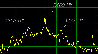
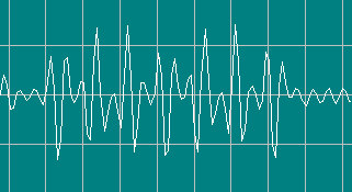
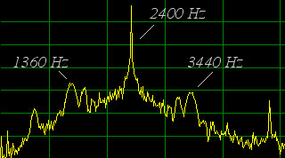
Channel sync:
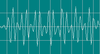
Channel A: series of square waves at 832 Hz, 7 cicles
Channel A: series of square waves at 1040 Hz, 7 cicles
Channel A: series of square waves at 832 Hz, 7 cicles
Oscilloscope
|
Spectrum
|
|---|---|
 |
 |
Channel A: series of square waves at 1040 Hz, 7 cicles
Oscilloscope
|
Spectrum
|
|---|---|
 |
 |
Subscribe to:
Posts (Atom)
